English
  Spanish
  Portuguese
  Arabic
  Russian
  简体中文
简体中文 

 Location:
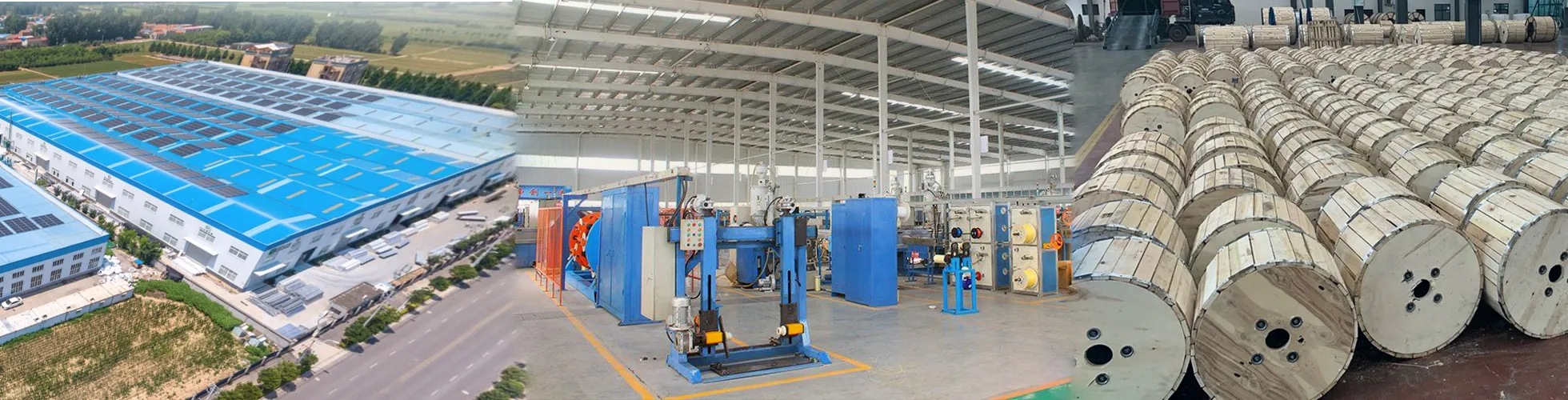
 ( 2 ) Illustrated Guide to Fiber Optic Cable Pipe Laying and Cable Construction
 Update Time:2025-12-13
 Traffic:
Pipeline Optical Cables
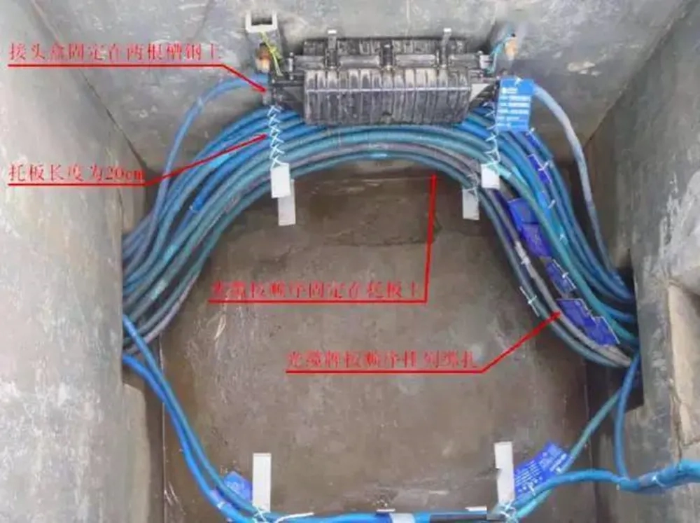
① The optical cable in the hand hole should be protected by a serpentine hose (or soft plastic tube). The laid optical cable should be close to the wall of the hand hole and tied to the bracket with a plastic tie or processed according to the design requirements; at the same time, it is necessary to ensure that the direction of the optical cable in the hand hole is smooth and there is no cross-twist phenomenon
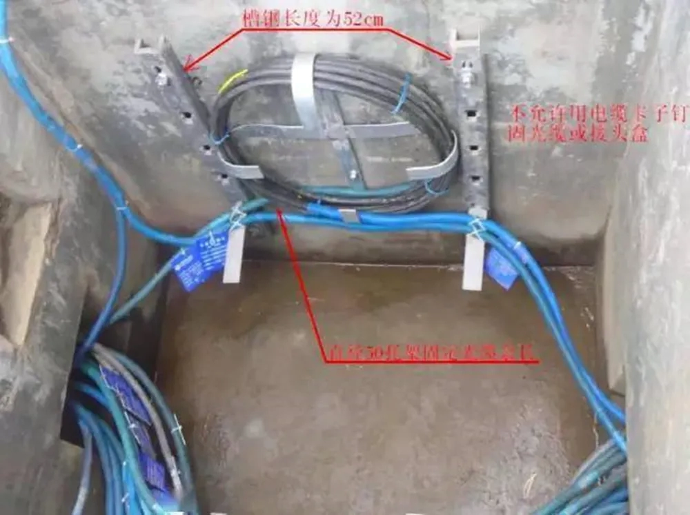
② Generally, 15 meters of optical cable is reserved in the base station lead-in well. If there are many old optical cables reserved in the lead-in well, the reserved optical cable should be one hand ahead. The well is reserved; 15 meters are reserved for every 500 meters of the straight section; 15 meters are reserved for the joint well; an additional 15 meters is reserved when the line passes through a bridge or sewer; the reserved optical cable is tied and fixed with tie wire according to regulations
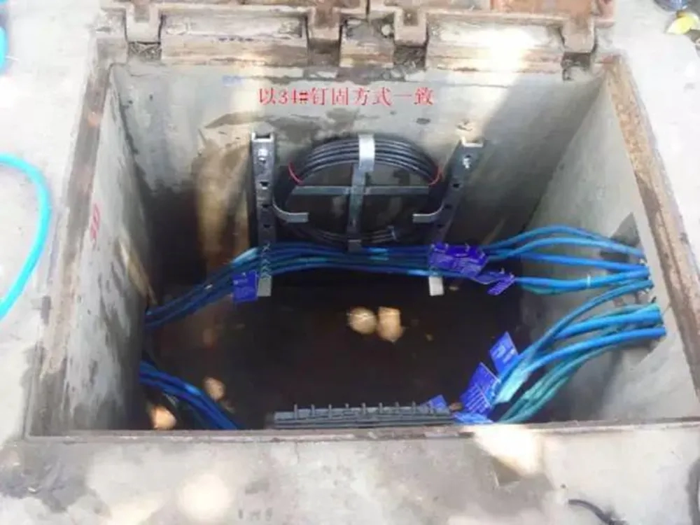
③In the hand hole, hang an optical cable identification plate about 35CM from the optical cable horn; an optical cable identification plate is also required at the optical cable reservation and joint
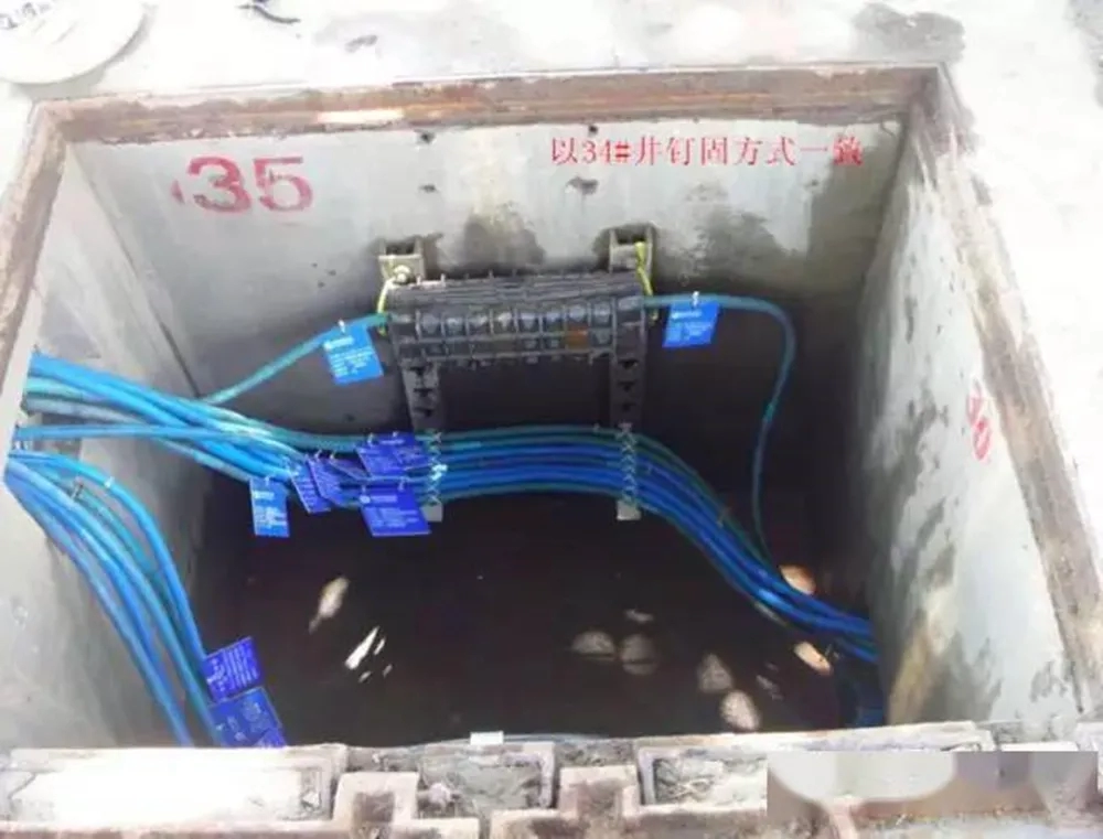
④The pipeline optical cable joint box is in the manhole (handhole), about 20-30 cm away from the wellhead, and the plate is connected Level with the ground; the joint box is fixed with expansion bolts; the optical cable reserved ring is fixed on one side of the well wall; the installation of the joint box and the position of the remaining cable coil should not affect the layout of other optical cable joints in the manhole
⑤ No bending is allowed within the 15cm length of the optical cable exiting the sub-pipe hole
⑥ The sub-pipe should be laid in full capacity with three or four colors according to the requirements of various cities. Multiple sub-pipes are arranged in color order with the same path. The sub-pipe is cut flat at a point not exceeding 10 cm from the exit hole (PVC large pipe hole) in the well, and a plug drum is put on. The empty sub-pipe without laying optical cables should be covered with a sub-pipe end cap
⑦ When laying optical cables through obstacles such as railways, roads, rivers, ditches, and other underground pipelines, specific location markings should be made or effective protection measures should be taken, and the manhole position should be safe
⑧ Check whether the pipeline route and length are consistent with the drawings
⑨ During the acceptance, if there are problems such as damage to the manhole, the manhole ring, the loss of the manhole cover, the uneven stakes, and other ancillary facilities, they should be raised in the acceptance report or meeting, and a rectification plan should be formulated.
90*120 straight hand well
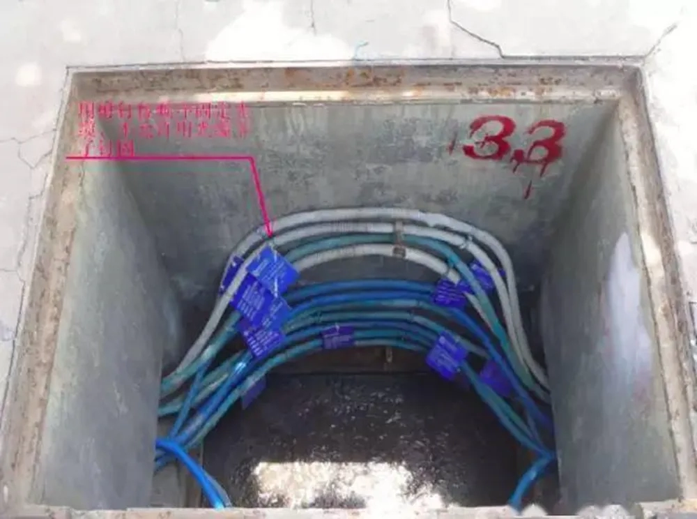
60*90 straight hand well
Overhead optical cable
① Check whether the pole line direction, pole wire (pole) buried position, pole height and pole distance, wire pulling pattern, cable joint position, remaining cable position, total length of pole line, etc. are consistent with the engineering design
② The optical cable at the pole must have a certain bend (and be protected by a hose - depending on the design), and the optical cable at the corner pole must be protected by a plastic hose
③ The overhead lead-in and lead-out points must be tied firmly and protected with steel pipes (required to be more than 2.5 meters)
④ The places where the overhead optical cable crosses or is parallel to the power line (not meeting the required spacing of the specification) must be Use three-wire cross protection sleeve for insulation protection
⑤ When overhead optical cables cross the intersection where vehicles pass, the crossing height must be ensured to be above 7 meters, and safety signs or signs must be hung on the suspension line; near-road poles and wires affect the line and traffic safety, and reflective signs must be made. If conditions permit, pole piers must be built for protection
⑥ For pole lines built together with optical cables, the poles must not be seriously skewed or marked, and the poles must not be broken or exposed
⑦ The wires must be diagonally deep and the ground anchors must not be more than 0.5 meters unearthed
⑧ The hooks are even and not out of place, the verticality of the suspension wires meets the specifications, and the optical cables and suspension wires do not cross
⑨ The optical cable joints are firmly installed, and the remaining bindings are neat and beautiful, meeting the design requirements
⑩ Every other pole or according to the design The design requires that a signboard be tied to the optical cable on the pole. The content of the signboard is the same as that of the pipeline optical cable. Within 500 meters of the in-and-out station, a signboard is tied to each overhead pole.
Incoming optical cable:
⑪The optical cable in and out of the incoming line room has a reserve that complies with regulations (generally 15 meters is reserved). The optical cables on the wiring rack (trough) are neatly tied, safe, and beautiful, without crossing or hanging. The optical cables are separated from other optical cables on each floor, turned, passed through the wall, and entered the distribution frame. Signboards should be hung at the turns. Plastic fiber tubes should be used for protection. When multiple cables are arranged, signs should be hung side by side at the same point
⑫No optical cables should be left on the floor wiring rack (trough) and the wiring rack in the machine room
⑬The first junction box out of the station Disconnect the electrical connection of the reinforcing core
⑭Fireproof mud or other materials that meet the design should be used to block fire and rodent when the optical cable passes through the floor or wall
Termination requirements
①The optical cable distribution frame (ODF) must be installed firmly and neatly, the cable stripping section to the fusion tray must be protected by hoses, the optical cable core fusion tray is placed firmly, the core fusion point is in the center of the heat shrink protective tube, and the core fiber is neat and undamaged
②Optical cable junction box: After the optical cable construction is completed, the optical cable inlet and outlet of the optical junction box must be blocked with glue and other items; the optical cable must be fixed with steel hoops in the optical junction box, and cannot be replaced with plastic ties; the optical fiber from the stripped end of the optical cable to the terminal box is connected with a plastic hose transition, and the wiring should be reasonable and beautiful.
③The printed optical cable name label (the name of the starting and terminal stations, the number of cores, and the length) should be affixed next to the connector, the optical fiber coupler bayonet should be installed neatly and firmly, and the bare fiber in the connection box should be passed through a small hose to the fusion tray and tied well.
④ The optical cable joint box should be installed firmly and tied neatly without water leakage;
⑤ Grounding requirements for the metal reinforcement core of the optical cable terminal: The metal reinforcement core and metal armor layer at the end of the ODF frame optical cable must be well grounded.
⑥ The pigtails in the ODF frame are neatly and safely laid, the fiber core numbers are accurate, and the spare fiber core pigtail connectors must be covered with end caps to prevent dust.
Transmission performance indicators
① Test method: Use a light source optical power meter to test the total loss value, and use a backscatter meter (OTDR) to test the average loss of the optical cable, joint loss, etc.;
② The average loss requirements for the entire single-mode optical cable: The average loss at a wavelength of 1550nm is 0.25db/km, and the average loss at a wavelength of 1310nm is 0.36db/km;
③ The loss of the intermediate joint of the single-mode optical cable: the loss of each fiber of the scattered optical cable is less than 0.08db, and the loss of each fiber of the ribbon is less than 0.1db, and the maximum does not exceed 0.15db.
④ Optical cable core termination loss: Each core loss including active coupler should not be greater than 0.5db.
⑤ The average attenuation of the optical fiber relay section (tested by light source optical power meter) must meet the design requirements, and the optical fiber backscattering curve should meet the requirements (printed by OTDR curve).
Line acceptance standard
① The buried depth of the optical cable line does not meet the standard requirements;
② The route selection of some lines is unreasonable, and some routes need to be relocated;
③ The two sides of the line hanging along the bridge are basically exposed to the outside, without protection measures, and there are hidden dangers of theft and fire;
④ The line spacing does not meet the requirements, and there are safety hazards in the three-line crossing protection;
⑤ The joint pipeline line is jointly built by multiple operators, and mobile lines are mixed in it, and the optical cable and pipeline lines are messy;
⑥ The mechanical and electrical performance of the pole line, pipeline, and optical cable does not meet the requirements. The specifications of the number pole, marking, etc. are not unified;
⑦ The crossing height of the optical cable line does not meet the requirements.